Project Description
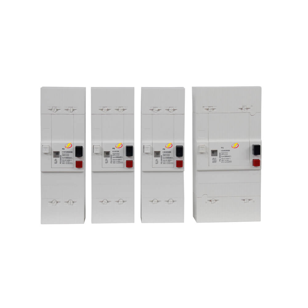
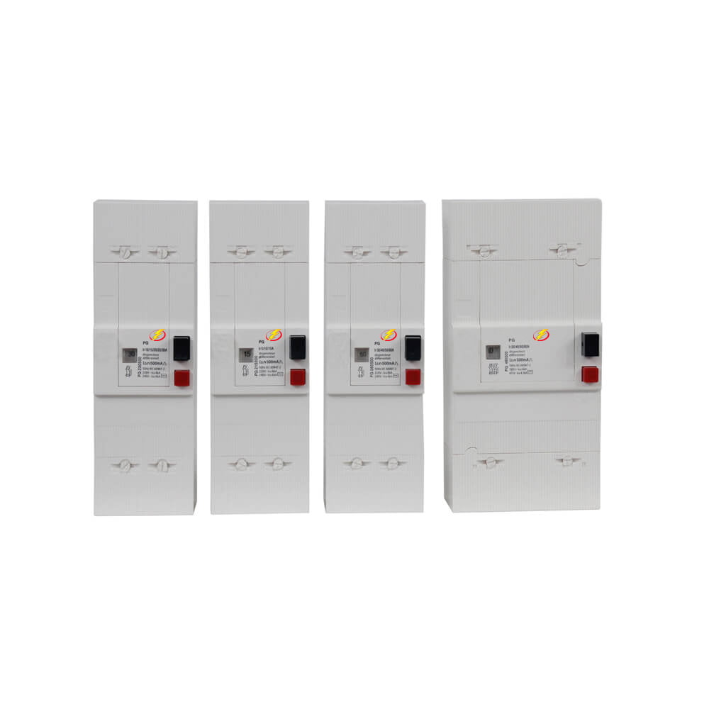
PG circuit breaker of 2P&4P with 300mA or 500mA ranges from 5 to 60 A, 2P (1 Ph + N) or 4P (3 Ph + N), with or without earth leakage protection (300mA-500mA or 650mA) good product to suit each type of installation. It complies with NFC 62-441, IEC60947-2 French standard.
Operating principles
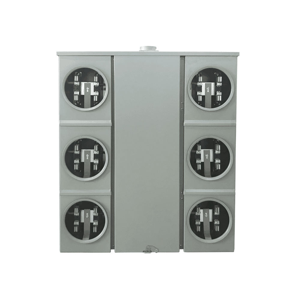
- Service connections are the interface between the Utility and the end user customer.
- They connect the customer’s electrical installation to the power distribution network.
Advantages
- Low-cost product, suitable for conventional service connections.
- Multiple rating device.
- Several levels of earth leakage sensitivity.
- Complies with the French NFC 61 450 standard.
Safety
■ Thermal compensation
□ The pole settings are not affected by the ambient temperature.
■ Residual current device
□ Highly reliable, self-powered system
□ Immunized against voltage surges of atmospheric origin
□ Uninterrupted power supply for greater user convenience.
■ Prevention of overvoltage
□ The neutral pole is designed to close first and open last to maintain a fixed potential.
Electrical characteristics
■ Earth leakage break time
□ < 0.2 s for 1 lAn
□ < 0.1 s for 2 lAn
■ Earth leakage tripping
□ 300 mA, 500 mA or 650 mA, self-powered
■ Operating temperature
□ – 5 * C to + 55 0 C
■ voltage drop
□ 1 pole + neutral < 0.9 V
■ Insulation resistance
□ > 2 MQ
■ Dielectric withstand
□ 2 kV AC for 1 minute
□ 4 kV between poles and frame
■ Tripping curve
□ C type
Other characteristics
■ Corrosion withstand
□ 8 days in damp chamber (CCTU4 cycle)
■ Weight:
□ 2-pole: 0.6 kg – 4-pole: 1.0 kg
Easy operation
■ Operation in all positions
■ ON/OFF control by push-button
■ Rating easily changed
■ Lead-sealable terminal shields
■ Captive terminal screws
■ Pivoting terminals
■ Copper cables up to 35 mm2
■ Neutral identified in blue
Environment
■ IP 40 protection
Prevention of overvoltage
- The neutral pole is designed to close first and open last to maintain a fixed potential.
Protection against nuisance tripping
- Immunized against voltage surges of atmospheric origin
- Uninterrupted power supply for greater user convenience
Display of contact position
- Green indicator: contact open
- Red indicator: contact closed
Safety checking
- The test button may be used to simulate an earth leakage fault, thereby providing a simple way to check the system.
Easy operation
– Operation In all positions
- ON/OFF control by push-button
- rating easily changed
- lead-sealable terminal shields
- captive terminal screws
- pivoting terminals
- copper cables up to 35 mm2
- neutral identified in blue
Function&Feature
| Tilting connection terminals fixing to wood or plastic panel 2 screws diameter 4mm |
| Poles not protected on the left, blue cap, marked N and the poles protected on the right |
| Test button for differential function |
| Poles not protected on the left, cap blue, marked N and protected poles at right |
| Plumbable terminal block (diameter 2 mm lead or plastic) on the screws |
Main Parameters
| Item | Description |
|---|---|
| Standards | NFC62-441; IEC60947-2 |
| Description of the poles | 2P(1Ph+1N)
4P( 3Ph+1N) |
| Provision of the neutral poles | Left |
| Caliber | 5A, 10A ou 15 A 10A, 15A, 20A ou 30A…….60A |
| Frequency | 50Hz or 60Hz |
| Setting | Plombable |
| Rated voltage | 250V AC 50/60 |
| Differential sensitivity | 500 mA |
| Voltage drop | < 0,3V |
| Insulation Resistance | >2MΩ |
| Differential Timing | Instantaneous |
| Protection | IP54 |

